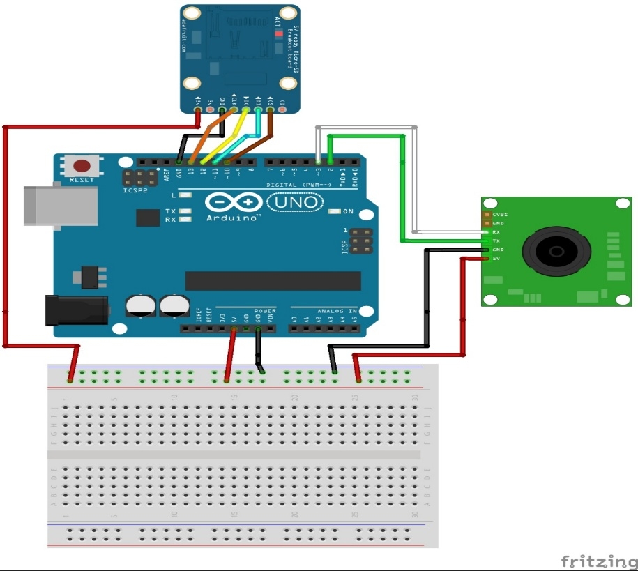

- EQUIPMENT NEEDED TO MAKE A ARDUINO CAMERA SERIAL
- EQUIPMENT NEEDED TO MAKE A ARDUINO CAMERA UPDATE
- EQUIPMENT NEEDED TO MAKE A ARDUINO CAMERA CODE
If you have a low frame rate or poor reception this might well be the problem. You can see the two different settings below: Click Start Stream to see a video stream from the camera.Ī few people have commented that they have received the board with the antenna jumper set for an external antenna rather than the on-board antenna. You should be able to see a GUI on the left where you can control elements of the camera, set face detection and face recognition.

Look for the IP address that the ESP32 has been given on your network.
EQUIPMENT NEEDED TO MAKE A ARDUINO CAMERA SERIAL
Press the reset button on the ESP32-CAM and watch the start up sequence in the serial monitor: Open the serial monitor via Tools > Serial Monitor. When the device has completed flashing, unplug IO0 from GND. Check that the IO0 pin (green in the diagram) is connected to GND and press the reset button under the module and try again. If you get an error that the device fails to connect. Open the Sketch by navigating File > Examples > ESP32 > Camera > CameraWebServer:Įdit the Sketch defines to look like this (assuming you are using the Ai-Thinker module): // Select camera modelĬhange the following two lines to match your WiFi connection details: const char* ssid = "NSA" Ĭlick Upload to build and flash the Sketch to your device. Plug in your module and change the board settings to these: There are now also power boards like the one below that make the connection much easier for uploading and reading the serial output. The green connection should be connected when flashing the module and disconnected when running. Wire the module according to the diagram above. You might be able to use the 5V from the side of the board to power the 5v pin on the camera. If you use a FT232 with 5v and 3.3v, set the voltage jumper to 3.3v. I found the top device worked fine but the FT232RL didn’t work for me. When using WiFi the ESP32 can use more current than is supplied via USB through these devices resulting in the module crashing and rebooting. The ESP32-CAM doesn’t come with a USB connector so you need either a CP2102 or a FT232RL USB to TTL Serial Converter to connect it to your PC.
EQUIPMENT NEEDED TO MAKE A ARDUINO CAMERA CODE
The face recognition code has been updated in the most recent versions (2.x.x) and no-longer works on ESP32 and ESP32-S2 based boards like this. To do this, open the Arduino IDE and in the menu: Tools > Board:xxxxx > Boards Manager:
EQUIPMENT NEEDED TO MAKE A ARDUINO CAMERA UPDATE
If you already have the ESP32 boards available in your IDE then you just need to update to the latest version of the board libraries.

If you’ve never used an ESP32 board in the Arduino IDE you need to follow the first part of this tutorial: ESP32 Built-in OLED Heltec WiFi Kit 32 Adding or Updating the ESP32 Range in the Arduino IDE There are other ESP32 based camera modules available that should work if the pins are set in the sketch. The ESP32-CAM module features an ESP32-S chip, an OV2640 camera and a microSD card slot. Setting up the ESP32-CAM with the Arduino IDE and Camera Web Server example.


 0 kommentar(er)
